This Switching Signal comes from the ignition control module. Run the engine at idle speed.

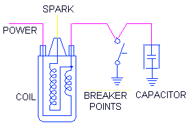
Coil condenser diagram.
How to wire an ignition coil. Locate the positive coil wire which runs from the ignition switch to the positive terminal of the ignition coil. On later model cars this wire may run back to the cars computer or the ignition control module. Step 2 Connect the positive coil wire to the positive terminal of the ignition coil.
The ignition coil is the part of your engine that produces high voltage in order to power your cylinders. The distributor is what gets that high voltage from the coil to the right cylinder. The connection is accomplished through a cap and rotor.
The ignition coil connects to the rotor and the rotor spins around inside the cap. Battery Ignition using external coil. How to properly connect this type of coil to your engine.
Sometimes substituted for a failed Magneto coil ignition syst. How to Wire 12 Volt Coils Step 1. Disconnect the black negative cable on the negative post of the battery.
Look at the ignition coil. These coils have one large terminal for the spark plug wire that runs over to the. Connect one end of the spark plug wire to the large center.
Your vehicles ignition coil sends an electrical signal from the computer to your spark plugs. A failing coil can result in a number of problems such a stalled vehicle rough idling or vehicle failure just to name a few. Replacing the ignition coil is a relatively simple and inexpensive process.
Part 1 of 1. Replacing an ignition coil. That graphic 12 Volt Ignition Coil Wiring Diagram How To Wire A Coil To Points with Ignition Coil Condenser Wiring Diagram previously mentioned is usually labelled using.
Coil condenser diagram. Published by means of Tops Stars Team on December 7 2013. Not electronic ignition just the original replacement old-fashioned 22 coil.
I have no reason to assume that it was wired correctly to begin with but the car came with three wires attached to the coil. One seems to be going through the firewall to what I assume to be the ignition itself The second wire is going to the alternator. Use the vehicle wiring diagram to identify the COP circuit functions.
Connect PicoScope Channel A to the coil signal circuit. Connect PicoScope Channel B to the coil feedback circuit. Run the engine at idle speed.
Minimize the help page. You will see that PicoScope has displayed an example waveform and is preset to capture your waveform. An ignition coil also called a spark coil is an induction coil in an automobiles ignition system that transforms the batterys voltage to the thousands of volts needed to create an electric spark in the spark plugs to ignite the fuel.
Some coils have an internal resistor while others rely on a resistor wire or an external resistor to limit the current flowing into the coil from the cars. Position the leads of the ohmmeter on the poles of the secondary coil. Next keep one lead on one of the outer contacts and touch the other to the central inner contact of the ignition coil where the main wire to the distributor connects.
Record the resistance reading - this is the resistance of the coils secondary winding. Install a Mallory Ignition Ballast Resistor Part No. Unscrew the bolts holding the coil in place using a wrench.
Depending on the size of the ignition coil it may be held on with anywhere from 1 to 4 bolts on most applications. Locate each bolt securing the coil in place and then use a socket of the appropriate size with a ratchet to loosen and remove the bolts. Locate coil packs or ignition coil in the engine bay.
If your car has a distributor follow the wire that is in the center of the distributor cap to find the igniton coil. Cars with coil packs usually have them mounted near a valve cover. Coil on plug ignition coils are typically placed near or directly over each spark plug.
How To Wire A Ballast Resistor Diagram Chevy 350 Ignition Coil Ignition Coil Wiring Diagram You Chevy 350 Ignition Coil Wiring Diagram November 4 2018 April 12 2020 Wiring Diagram by Anna R. Compare the new ignition coil to the old ignition coil to ensure that both are the same design. Position the coil over the spark plug.
Make sure the coils mounting hole lines up with the stud or hole on the engine. Press down on the coil gently. One wire of the Coil-On-Plug ignition coil is the Power Circuit that delivers 12 Volts.
The other wire is the Switching Signal Circuit. This Switching Signal comes from the ignition control module. This module may be in the ECM or mounted somewhere in the engine compartment.
Three basic tests are done to test that these signals are indeed.