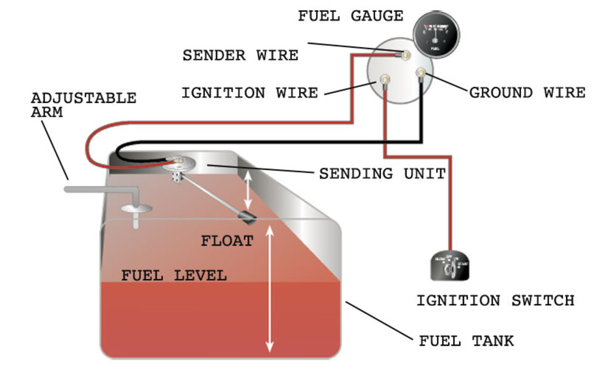
Install the new gauge reconnect the wiring and turn on the power. The most important thing to remember is that the gauge and the sending unit must be a.

S for the sender G or for the ground and I for the ignition.
Wiring diagram for fuel gauge. February 18 2019 by Larry A. Wellborn Assortment of fuel gauge sending unit wiring diagram. A wiring diagram is a simplified traditional photographic representation of an electrical circuit.
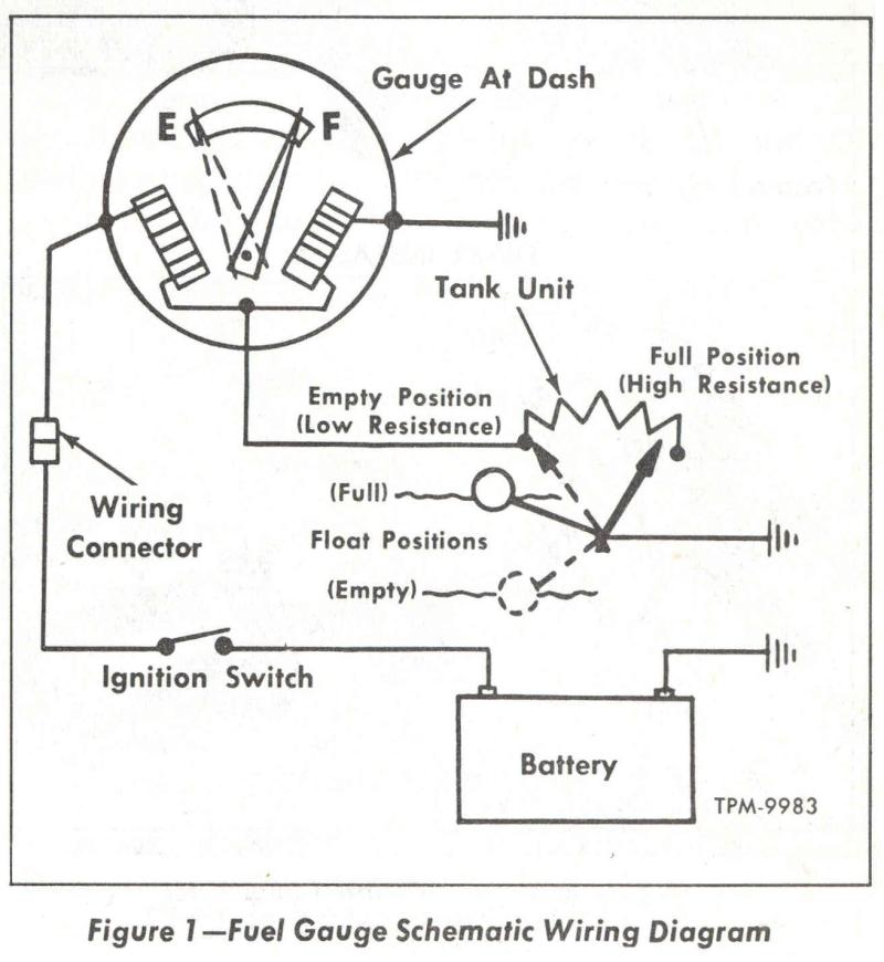
It shows the elements of the circuit as streamlined forms as well as the power as well as signal links between the devices. Moeller Gauge-Wiring Diagram 4 Universal Electric Fuel Sender Instructions Electric Fuel. Gauge pointer should be at the position shown in the lower portion of the diagram.
To test senders the resistance values are shown at minimum and full gauge scales. Fuel Systems Marine Voltage - I to G terminal - 10 to 16 volts. Test gauge as follows.
Check the wiring diagram that comes with the kit and mark the back of the new fuel gauge with symbols for each post. S for the sender G or for the ground and I for the ignition. Install the new gauge reconnect the wiring and turn on the power.
The fuel gauge should now show the correct fuel level in. About Press Copyright Contact us Creators Advertise Developers Terms Privacy Policy Safety How YouTube works Test new features Press Copyright Contact us Creators. Wire a fuel gauge by first disconnecting the old dysfunctional unit to replace it with a new one.
Obtain 12-volt power from the fuse box using a standard wire and connect it to the positive terminal of the fuel gauge. Next connect a wire from the float on the fuel tank to the negative terminal of the fuel gauge. Gm Fuel Gauge Schematic Fuel Gauge Troubleshooting Wiring Diagrams with Equus Fuel Gauge Wiring Diagram image size 769 X 289 px and to view image details please click the image.
Here is a picture gallery about equus fuel gauge wiring diagram complete with the description of the image please find the image you need. These will be labeled S for the fuel-sender signal wire for the 12V positive wire - for the 12V negative wire and the last will be the gauge-light power wire. Step 2 Connect the end of the - wire to a bare-metal surface on the vehicle.
This video will help you troubleshoot your fuel gauge and sending unit to verify if it is good or needs to be replaced. The fuel gage circuit consists of the sending unit in the fuel tank the gauge in the dash and the wiring and dash wiring or circuit board between them. Its power source comes from a voltage regulator that is 5 volts.
NEVER HOOK THE SENDING UNIT OR GAUGE TO A 12 VOLT BATTERY Here is a picture of a sending unit on a 1988 Bronco II wiring. Smiths Fuel Gauge Wiring Diagram wiring diagram is a simplified tolerable pictorial representation of an electrical circuitIt shows the components of the circuit as simplified shapes and the knack and signal contacts with the devices. Amp Gauge Wiring 1 Always disconnect the ground lead from the vehicle battery before wiring any gauge.
2 Classic Instruments Amp gauge should only be used on vehicles with alternators rated at 60 Amps or less. Using an alternator with higher output capacity is dangerous and could cause a fire. Wiring a fuel gauge is much the same as wiring any other gauge on your boat.
One wire comes from the ignition to the instrument one wire comes from the sensor to the instrument one wire comes to the instrument light and one wire from the instrument goes to the boats common ground. The wires may follow a seemingly unusual path but the system. Installing a Fuel Gauge and Sender.
Jim Clark the Hot Rod MD. Here is the finished end in the engine compartment where a short fuel hose will complete the connection from the fuel tank to the fuel pump. Wiring for the gauge chosen will vary depending on the application.
Instructions for this are usually included with the gauge package. FUEL LEVEL GAUGE WIRING Figure 4. Disconnect negative - battery cable.
Wire connect the G terminal to a clean rustpaint-free Figure 4ground. Using 18 gauge wire connect the I terminal to a switched 12V source. Using 18-gauge wire connect the S sender terminal of the gauge to the fuel level sender.
Fuel within Stewart Warner Gauges Wiring Diagrams image size 429 X 298 px and to view image details please click the image. Truly we have been noticed that stewart warner gauges wiring diagrams is being one of the most popular subject right now. So that we attempted to find some good stewart warner gauges wiring diagrams picture to suit your needs.
Marine Fuel Gauge Wiring Diagram Download. Variety of marine fuel gauge wiring diagram. A wiring diagram is a simplified standard pictorial depiction of an electrical circuit.
It shows the parts of the circuit as simplified shapes and the power as well as signal links between the devices. A fuel gauge on a tractor works the same as an automotive fuel gauge. The most important thing to remember is that the gauge and the sending unit must be a.
Need a wiring diagram for a massey ferguson tractor lookin for a complete fuel gauge wiring diagram fuel gauge doesnt work how to wire fuel guage onFuel gauge wasnt working so I ordered a. Diagram Vdo Gauges Wiring Sdometer Full Version Hd Quality Objectdiagram Digitalight It. Dolphin gauges wiring diagram land quad 93 diagrams 2001 lower radiator 2004 vdo tach auto 95 7600 56 chevy gas gauge full installation instructions for 3 8 schematic sdometer shark hotrod a tpi tech gm pulse generator 1988 tachometer national hd need help steam tables properties 1974 el camino fuse box.
Jeep Grand Cherokee Fuel Gauge Wiring Diagram Series Bronco B Ilcovodelpirata It. 1988 jeep cherokee fuel pump wiring 1996 grand diagram 1999 gas gauge 1994 sony forum 88 1995 sport full 95 injector 2011 1998 xj filter location 2000 1993 2006 lincoln ls engine harnes harness l diagrams were can i find an ecu 1991 relay for ignition coil 4 0l 1997 laredo connector cylinder number 3 7 fuse box.